Description:
1.BMS For 4S /12V LiFePO4 Battery Pack2.Maximal continuous Discharging current:70A
3.We have 10A-100A bms
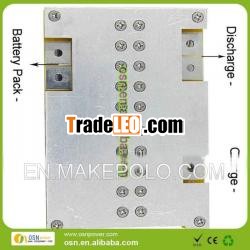
BMS Specifications For 4S /12.8V LiFePO4 Battery Pack
| |||
Model:OSN-4S7020-BMS | |||
No. | Test item | Criterion | |
1 |
Voltage | Chargingvoltage | DC:14.4V3.6V/Cell |
Balancevoltage for single cell | 3.600.025V | ||
Balancecurrent for single cell | 7210mA | ||
2 | Current | Currentconsumption for single cell | ≤20μA |
Maximalcontinuous Charging current | 20A | ||
Maximalcontinuous Discharging current | 70A | ||
3 | Over chargeProtection | Over chargedetection voltage | 3.900.025V |
Over chargedetection delay time | 0.5—2S | ||
Over chargerelease voltage | 3.800.05V | ||
4 | Overdischarge protection | Overdischarge detection voltage | 2.000.05V |
Overdischarge detection delay time | 10-300mS | ||
Overdischarge release voltage | 2.300.05V | ||
5 | Over currentprotection | Over currentdetection voltage | 0.62V |
Over currentdetection current | 20020A | ||
Detectiondelay time | 5ms—20mS | ||
Releasecondition | Cut load,Automatic Recovery | ||
6 | Shortprotection | Detectioncondition | Exteriorshort circuit |
Detectiondelay time | 200-500us | ||
Releasecondition | Cut load,Automatic Recovery | ||
7 | Resistance | Protection circuitry(MOSFET) | ≤20mΩ |
8 | Temperature | Operating Temperature Range | -40~85°C |
Storage Temperature Range | -40~125°C | ||
9 | Size |
| L120*W80*T25mm |
10 | Weight |
|
|
11 | MotorPower |
| 850W orbelow |
MainFunctions:
The producthas 6 main functions: over charge, over discharge, over current,short circuits, balancing and low-current lock.
1.Function of over charge protection: once voltage of any battery inthe pack gets higher than the over charge protection point, chargecuts off to ensure all batteries work within the over chargeprotection point.
2.Function of over discharge: once voltage of any battery in the packgets lower than the over charge protection point, discharge cutsoff to ensure all batteries work beyond the over charge protectionpoint.
3.Function of over current: during the discharge process of batterypack, once discharge current gets over the set over currentprotection point, output cuts off to ensure battery pack workswithin the safe limit of current.
4.Function of short circuit protection: once battery pack’s outputport appears the condition of short circuit, it cuts off to ensurebattery group not to be damaged because of shortcircuit.
5.Function of voltage balancing: in the late charging period ofbattery pack, voltage difference that appears during the usingprocess of each battery could get balancing revised to ensurebattery pack’s capacitance.
6.Function of low-current lock: series connection of low-current lockgets reserved and low current controls on-and-off of the main highcurrent to make it safer and more convenient.
Ways ofline-connection:
The following proceduresshould be accorded with the referrence ofdrawings:
1.Weld a powersupply line with the proper diameter from the B- port of guardshield and connect it with negative pole of battery pack(B-);
2.Connect line 1signed in the line-connection drawing with the second battery''spole in the battery pack;
3.Connect line 2 signed in theline-connection drawing with the third battery''s pole in thebattery pack;
4.Connect line 3signed in the line-connection drawing with the fourth battery''spole in the battery pack;
5.Connect line 4signed in the line-connection drawing with the fifth battery''spole in the battery pack;
6.Connect the redline on the highest position signed inthe line-connectiondrawing with the last battery''s positive pole in the batterygroup;(different signal lines'' connection could be operated withthe above reference)
7.A power supplyline with the proper diameter led from the battery pack''s positivepole (B ) and another similar line led from the guard shield''s P-should be respectively connected with the positive and negativepoles of the load.
8.A power supplyline with the proper diameter led from guard shield''s C- andanother power supply line led from the battery pack''s positivepole (B ) should be respectively connected with the negative andpositive poles of the charger.
Usage andAttention:
1. Please strictlyfollow the directions to connect the PCB to the battery. Usuallythere''s voltage in the battery at all time, so operator shouldconnect one single line after other starting from terminal B,following the order from low voltage to high voltage, otherwise itcan cause irreparable damage.
2. During the installation, pay attention to smallmetallic particles that can stick to the protectionboard.
3.Follow the standard rules when makingconnections between the protection board and the lithium-ionbattery. Operator should not run any wire across the back of theprotection board. Keep them along the side of the boardinstead.
4.When setting up the protection board, be sure touse a hard epoxy board as an interlayer, to prevent short-circuitcaused by the components on the back of the protectionboard.
5.Both resistive load and inductive load can beused to test battery packs that use this PCB, but not electronicload. Testing with an electronic load will lead to the breakdown ofthe MOS components on the protection board.
6.Select proper wire gauge to prevent temperatureincrease from high discharge current (when wire gauge is too high)and excessive voltage drop (when wire gauge is too low).
7.When the PCB is to be installed inside thebattery''s housing, the user must fully take heat/electricinsulation and tightness into account to prevent internal shortcircuit.
8.Keep any fully charged battery away fromchildren.
9.If any abnormality is detected during use,please stop using the product immediately and notify professionaltechnician to conduct inspection and maintenance.

