

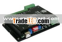
| Step motor device | Programmable | Current per phase, Amp | Power supply, VDC | Microstepping mode | Operation mode |
| SMSD-4,2 | USB, virtual RS-232 | 0,42 – 4,2 | 12-48 | 1, 1/2, 1/4, 1/16 | STEP/DIR |
SMSD step motor controller is our development, which includes a driver for stepper motor commutation and a logic controller for realizing different types of motion in one case. SMSD step motor controllers provide 3 main types of motor control:
1) Driver mode with logic signals STEP/DIR. SMSD stepper controller can operate as simple stepper driver. Logic signals STEP (Pulse) and DIR (voltage level) are assign motion of a stepper motor. In this mode the motion distance depends on a number of STEP signals (voltage pulses), velocity of stepper motor is proportional to the STEP signals frequency. The motion direction depends on the voltage level on the DIR input – 0VDC is low level and 5-24VDC is high level.
Motion can be stopped by EN signal: low level 0VDC allows motion, high voltage level 5-24VDC prohibits motion.
- Pulse/Dir mode – step motor driver receives voltage pulses as Step signal and voltage level as Direction signal. Motion displacement depends on pulses number, motion speed is proportional to pulses frequency. The direction depends on voltage level on DIR input. This mode is wide-spread by host controllers and accepted for control via LPT port of a computer (For CNC machines, as an example).
- CW/CCW mode – A-phase + B-phase pulse signals – two phase pulse train with 90° difference. Motion displacement depends on one-chanel pulses number, motion speed is proportional to pulses frequency. The direction depends on leading phase – A or B. This mode can be applied by some host controllers or 2-channel incremental encoders, selsyns and self-synchronous devices.
2) Manual operation mode of SMSD stepper controller provides analog speed control. A step motor rotates permanently, speed is adjusted by internal or external potentiometer or is proportional to analog voltage signal 0-5VDC.
For system integration digital inputs are provided in SMSD step motor controllers in manual mode:
- one digital reverse input;
- one digital emergency input.
3) Program mode and preset motion algorithm. All operation parameters for SMSD stepper controller are set by commands from computer: speed, acceleration and deceleration, direction, distance, pauses, cycles, waiting for external signals, turn on/off programmable relay for output signals. The sequence of the commands is stored in EEPROM (that is non-volatile memory). After commands are set into the stepper controller, SMSD can operate in standalone mode or from the computer.
Connection to a computer is provided via USB. Communication interface is RS-232 (virtual COM). Cable and GUI program for windows is included to package.
For system integration digital inputs are provided in SMSD step motor controllers:
- two programmable digital inputs;
- one digital reverse input;
- one digital emergency input;
- one digital input for home positioning.

